Mashbot kit index
Love Notes and Intimate Circuits
Helen J. Burgess
North Carolina State University
 Instruction Set: Setting Up the Board and Printer
In this section we'll be running through instructions for setting up both the printer itself and the Arduino microcontroller and breadboard that feed information to it from the internet. James Adams at exciting.io has done a wonderful and very thorough job of documenting this process, and I'm relying heavily on his backend infrastructure for this project. However, instead of using an Arduino plus a separate ethernet shield as he does, I'm using a combined one, which will require a couple of extra steps to get your Arduino environment set up right. I'll detail this alternative setup, and (rather than repeat what's already out there) provide a circuit diagram for setting up the board. If you want close, step-by-step instructions for wiring up the board, go here: https://github.com/exciting-io/printer/wiki/Making-your-own-printer.
I: Shopping List
An internet connection
The printer configuration for this project is via ethernet, so you'll need to have access to an ethernet port. See my note on networking at the bottom of this page.
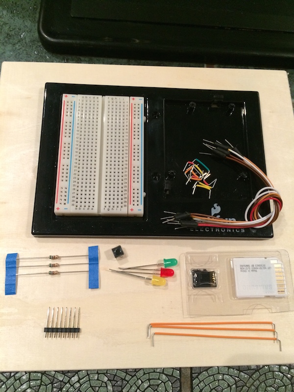
Things you'll need for the controller:
- Arduino Ethernet combined board (https://www.sparkfun.com/products/11229)
- Mini Breadboard
- 4x 560 ohm resistors - (green, blue, red/brown, gold stripe)
- 1 x small push button
- 3 x LEDs (one each of red, green, yellow)
- Breadboard jumper wires. For a good selection, I suggest getting something like this: https://www.sparkfun.com/products/124
- Header pins
- A micro SIM card, FAT-32 formatted, at least 2GB
Things you'll need for the printer:
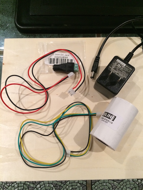
- The printer, of course.You can get them various places; I got mine from Adafruit here: https://www.adafruit.com/products/597 but Sparkfun also stocks them. The printer comes with two cables: one for data and one for power.
- Female 2.1mm jack terminal block adapter like this: https://www.adafruit.com/products/368
- A 5 volt DC 2A wall adaptor cable with barrel jack to power the printer
- Roll of thermal paper like this: https://www.sparkfun.com/products/10560
Cables:
- An ethernet cable
- A cable to upload your code to the Arduino. For an Arduino Ethernet, this should be an FTDI cable: https://www.sparkfun.com/products/11229
- A cable to power your arduino. You can use the same FTDI cable you use to upload your sketches, a barrel jack wall adaptor, or a barrel jack battery adapter like this: https://www.sparkfun.com/products/9518
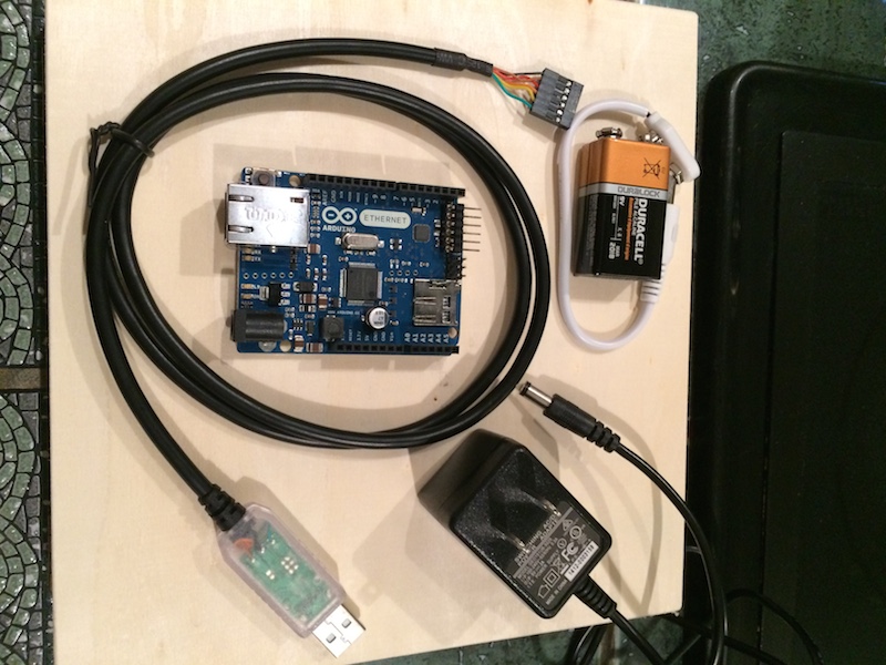
FTDI cable, barrel jack battery adapter, 5V 2A wall adapter.
II: Setup: The Arduino
I'm kind of assuming you know a little about Arduino, and you know where to get the IDE (the development environment). If you've forgotten, though, go here to get it.
- Before you start, make sure you have the right drivers for the Arduino Ethernet board to communicate with your IDE.
- download a copy of the driver for your FTDI cable here: http://www.ftdichip.com/Drivers/VCP.htm
- Plug the Ethernet board and your computer together using the FTDI cable. The non-USB end goes into those 6 pins sticking out the end of the board:
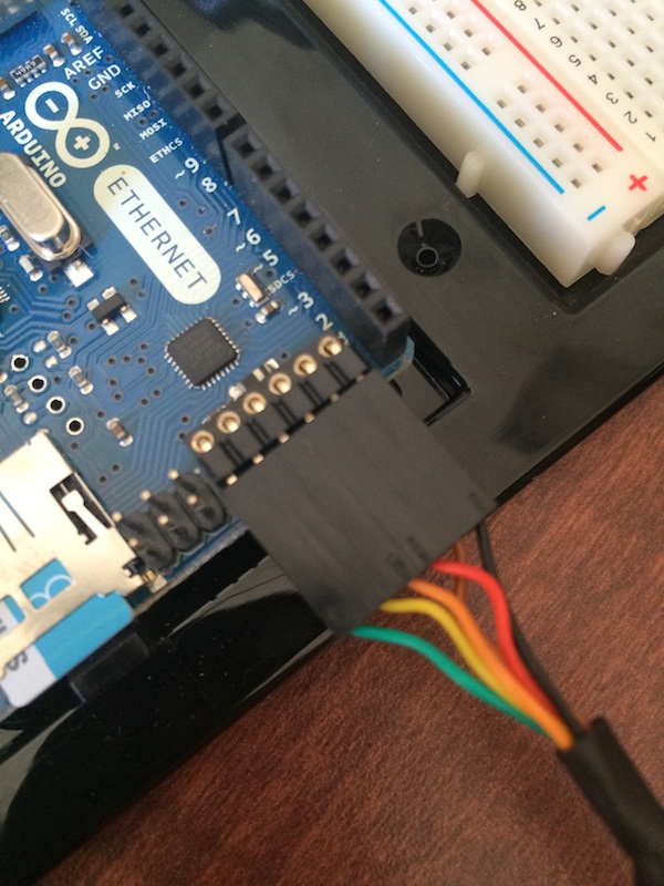
FTDI cable, talking to the Arduino board. - Go to "Tools > Board" and choose "Arduino Ethernet." Then check "Tools > Port." If you don't see a USB port listed (mine starts with /dev/cu/usbserial) then you'll need to go to https://hofmannsven.com/2012/laboratory/arduino-ethernet/ to download a driver.
- restart, because sometimes these things don't stick. Computers.
- Now that your computer is talking to your board, go get a copy of exciting.io's "printer.ino" sketch. I've provided it here for easy download: https://github.com/hyperrhiz/printer/blob/master/printer.ino
- Load the sketch into your Arduino environment.
- Look underneath your arduino board. There should be a sticker there that lists the MAC address of the board. Write it down.
- now, go to line 11 in the code sketch. it should read something like:
byte mac[] = { 0x90, 0xA2, 0xDA, 0x0D, 0x92, 0xCB }; // physical mac address
You'll need to replace those values with your own. Say your MAC address is AB-90-DA-B3-92 -BD, you'll go in and replace the last two digits of each number in the sketch:
byte mac[] = { 0xAB, 0x90, 0xDA, 0xB3, 0x92, 0xBD }; // physical mac address - if you also got ambitious and set up the entire server on your own host, you should change the listing on line 25 from this
const char host[] = "printer.exciting.io"; // the host of the backend server
to this
const char host[] = "yourservername.goes.here"; // the host of the backend server
- Upload the sketch to your Arduino. Now you can disconnect the FTDI cable if you want to, because it's time to wire up the breadboard! Rather than steal Exciting.io's thunder, I'll let them show how it's all wired up step by step on their wiki: https://github.com/exciting-io/printer/wiki/Making-your-own-printer. But to shorten everything up, here's a circuit diagram with everything you need to know.
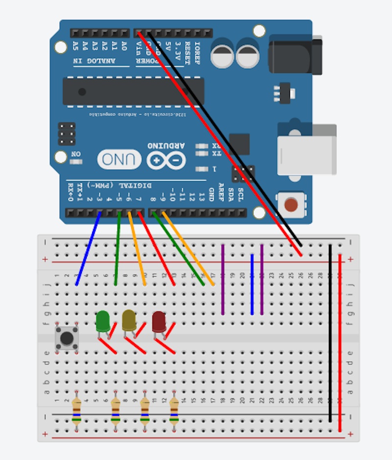
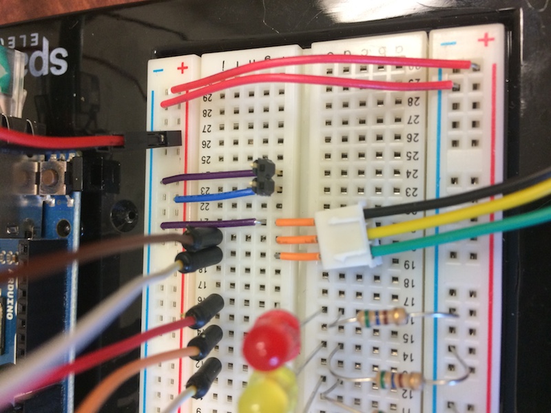
On the Arduino end, the jumper wires are connected as follows:
- Button wire: digital pin 3
- LED wires: pins 5,6 ,7
- Printer data wires: pins 8 (green) and 9 (yellow)
- Power wires to vin (from + rail) and ground (from - ground rail)
III: Setup: The Printer
Once it's all wired up, let's move on to the printer. This is a cool little machine that uses thermal paper to print data, identical to a receipt printer.
- There are two cables provided with the printer. The red/black combo will be for your power; the yellow/green/black will provide the data from the Arduino. They plug into the bottom of the printer.
- in order to get power to the printer, you'll need to do a little surgery. Look at the red/black cable and you'll see it has one end with three holes (which fits into the printer) and one end with two. You want to connect this up to the wall power source.
- cut off the TWO-end of the cable. Using wire strippers, very delicately remove a little of the plastic cable covering, so your wires look like below.
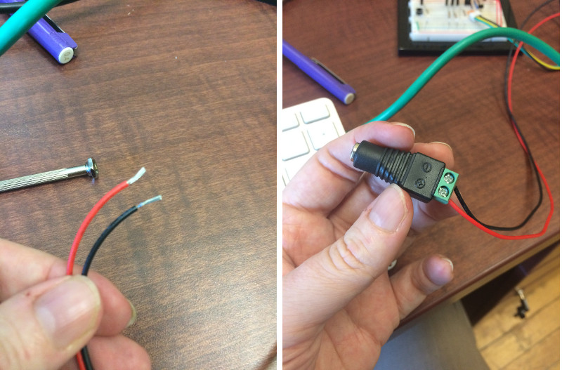
Left: stripped wires. Right: put these into the barrel adapter & tighten the screws. - poke the wire endings into the barrel jack adapter (undo the teeny tiny screws, push the wires in, and then tighten the screws). Put the BLACK wire into the - hole, and the RED wire into the + hole.
- now you'll have a nice adapter at the end of your power cable, and you can plug your wall adapter straight in there.
- cut off the TWO-end of the cable. Using wire strippers, very delicately remove a little of the plastic cable covering, so your wires look like below.
- plug the cables into the printer. Other things to know:
- when you drop the paper in, make sure the paper is feeding from underneath, not over the top of the roll.
- when you close the lid, it will feel like the paper is stuck. It's not - it will feed through just fine.
- At this point, it's a good idea to do a test print before you hook it up to the breadboard. Hold down the print button while plugging the power in (this will require your extra cyborg hand). It should print out a nice pile of garbage.
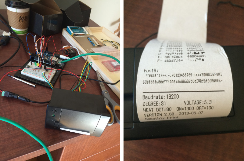
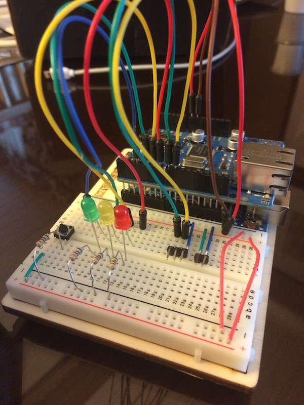
Left: all wired up. Messy but it works. Right: test print. - Finally, connect your data cable (green/yellow/black) to the three header pins on your breadboard (labeled on the circuit diagram). The green wire goes to the left, closest to the LEDs and button. You'll notice I am using little orange headers; that's because I broke my header pins bending them. Either will work just fine.
IV: The Moment of Truth
- Plug the Arduino power cable or battery in (use your FTDI cable or a battery adapter), and your ethernet cable as well. The other end of the ethernet cable should go to the back of your router, into your wall, or into a computer bridge, depending on how you have your network set up - see my note below.
- If all goes well, you should see a whole bunch of lights go on, and eventually the YELLOW LED on your breadboard will settle in to flashing every 10 seconds. This means you're connecting successfully to the backend server provided by exciting.io.
- Get your printer's unique network ID. You'll need it to be able to get data. Go to http://printer.exciting.io/my-printer, and make a note of the long alphanumeric id number.
- While you're there, you can also do a test print to make sure everything's good.
- Protip: if your resulting printout is partially missing, go back and look at the input box on the printer page that sets the darkness level. It's likely set to around 400 - cut that number down (I used 100) until the test print looks good.
Addendum: A Note About Networking
If you're planning on running this printer at work or in a public installation, you should be forewarned about potential networking issues. Here's the problem: in order to get onto the internet, you have to deal with security. If you're working on this from home, you can most likely plug the ethernet cable into your home router and call it a day. If you're somewhere else, though, you'll need to be creative. My solution was to share my wireless access from my Mac laptop to a USB ethernet cable, and plug that into the Arduino ethernet port:
- connect the ethernet cable to your computer. If you're using a laptop, you'll most likely need a USB adapter. Connect the other end to the Arduino board.
- go to System Preferences > Sharing. You're going to share your connection FROM "Wi-Fi" TO "USB Ethernet." When you check the Internet Sharing box on the left you'll probably get some warnings. Go ahead and do it anyway. Life is short.
- if you get a "cannot be shared" warning, the wifi network likely has too much awesome security to let you on. You may be out of luck. Try another network.
OK, on to Twitter!